G6000
ExcEpTionally SofT, highly coMprESSiblE gap fillEr
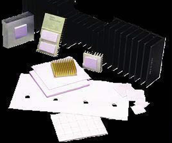
G-filler™ 6000 is an exceptionally soft, highly compressible gap filling interface pad
with a thermal conductivity of 3 W/mK. These outstanding properties are the result
of a proprietary boron nitride filler in the composition.
The high conductivity, in combination with extreme softness produces incredibly low
Details
ExcEpTionally SofT, highly coMprESSiblE gap fillEr
G-filler™ 6000 is an exceptionally soft, highly compressible gap filling interface pad
with a thermal conductivity of 3 W/mK. These outstanding properties are the result
of a proprietary boron nitride filler in the composition.
The high conductivity, in combination with extreme softness produces incredibly low
thermal resistances.
While extremely soft, G-filler™ 6000 recovers to over 90% of its original thickness
after compression under low pressure. G-filler™ 6000 is naturally tacky and requires
no additional adhesive coating that can inhibit thermal performance. G-filler™ 6000 is
electrically insulating, stable from –45°C to 200°C and meets UL 94 V0 rating.
fEaTUrES anD bEnEfiTS
• Very high compressibility for low stress applications
• 3 W/mK thermal conductivity
• Available in thicknesses from 0.020” - 0.200” (0.5mm - 5.0mm)
• Natural y tacky, needs no further adhesive coating
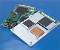
applicaTions
• Cooling components to the chassis or frame
• High speed mass storage drives
• RDRAM memory modules
• Heat pipe thermal solutions
• Automotive engine control units
• Telecommunications hardware
|
G-FILLER™ 6200 |
G-FILLER™ 6400 |
G-FILLER™ 6600 |
G-FILLER™ 6800 |
G-FILLER™ 6100 |
TEST METHOD |
|
|
Construction & Composition |
Reinforced boron nitride filled silicone elastomer |
Boron nitride filled silicone elastomer |
Boron nitride filled silicone elastomer |
Boron nitride filled silicone elastomer |
Boron nitride filled silicone elastomer |
|
|
Color |
Blue-Violet |
Blue-Violet |
Blue-Violet |
Blue-Violet |
Blue-Violet |
Visual |
|
Thickness |
0.020" (0.51mm) |
0.040" (1.02mm) |
0.060" (1.52mm) |
0.080" (2.03mm) |
0.100"(2.54mm) |
|
|
Thickness Tolerance |
± 0.003" (± 0.08mm) |
± 0.004" (± 0.10mm) |
± 0.006" (± 0.15mm) |
± 0.008" (± 0.20mm) |
± 0.010" (± 0.25mm) |
|
|
Density |
1.38 g/cc |
1.34 g/cc |
1.34 g/cc |
1.34 g/cc |
1.34 g/cc |
Helium Pycnometer |
|
Hardness |
40 Shore 00 |
25 Shore 00 |
25 Shore 00 |
25 Shore 00 |
25 Shore 00 |
ASTM D2240 |
|
Tensile Strength |
N/A |
15 psi |
15 psi |
15 psi |
15 psi |
ASTM D412 |
|
% Elongation |
N/A |
75 |
75 |
75 |
75 |
ASTM D412 |
|
Outgassing TML (Post Cured) |
0.13% |
0.13% |
0.13% |
0.13% |
0.13% |
ASTM E595 |
|
Outgassing CVCM (Post Cured) |
0.05% |
0.05% |
0.05% |
0.05% |
0.05% |
ASTM E595 |
|
UL Flammability Rating |
UL 94 V0 |
UL 94 V0 |
UL 94 V0 |
UL 94 V0 |
UL 94 V0 |
E180840 |
|
Temperature Range |
-45°C to 200°C |
-45°C to 200°C |
-45°C to 200°C |
-45°C to 200°C |
-45°C to 200°C |
ASTM D5470 (modified) |
|
Thermal Conductivity |
3 W/mK |
3 W/mK |
3 W/mK |
3 W/mK |
3 W/mK |
|
|
Thermal |
||||||
|
Impedance |
0.46 °C-in2/W |
0.62 °C-in2/W |
0.85 °C-in2/W |
1.09 °C-in2/W |
1.23 °C-in2/W |
ASTM D5470 |
|
@ 10 psi @ 69KPa |
2.97 °C-cm2/W |
4.00 °C-cm2/W |
5.50 °C-cm2/W |
7.04 °C-cm2/W |
7.94 °C-cm2/W |
(modified) |
|
Thermal Expansion |
6000 ppm/°C |
430 ppm/°C |
430 ppm/°C |
430 ppm/°C |
430 ppm/°C |
IPC-TM-650 2.4.24 |
|
Breakdown Voltage |
3,000 Volts AC |
>5,000 Volts AC |
>5,000 Volts AC |
>5,000 Volts AC |
>5,000 Volts AC |
ASTM D149 |
|
Volume Resistivity |
2 x 10¹³ohm-cm |
2 x 10¹³ohm-cm |
2 x 10¹³ohm-cm |
2 x 10¹³ohm-cm |
2 x 10¹³ohm-cm |
ASTM D257 |
|
Dielectric Constant @ 1MHz |
3.31 |
3.31 |
3.31 |
3.31 |
3.31 |
ASTM D150 |
STanDarD ThicKnESSES
0.020" (0.51mm) 0.030" (0.76mm) 0.040" (1.02mm) 0.050" (1.27mm)
0.060" (1.52mm) 0.070" (1.78mm) 0.080" (2.03mm) 0.090" (2.29mm)
0.100" (2.54mm) 0.110" (2.79mm) 0.120" (3.05mm) 0.130" (3.30mm)
0.140" (3.56mm) 0.150" (3.81mm) 0.160" (4.06mm) 0.170" (4.32mm)
0.180" (4.57mm) 0.190" (4.83mm) 0.200" (5.08mm)
Consult the factory for alternate thicknesses
STanDarD ShEET SiZES
9" x 9" (229mm x 229mm)
18” x 18” (457mm x 457mm). 9” x 9” only over 0.100” thickness.
G-fillerTM 6000 can be die cut to individual shapes. Pressure sensitive adhesive is not
applicable for G-fillerTM 6000 products.
TacKy onE SiDE only
G-filler™ 6000 is natural y tacky on both sides. G-filler™ 6000 can be provided tacky on
one side only. This is indicated by the suffix “DC1”.
This option offers good separation properties al owing the tacky side to stick to the
heatsink/chasis/cold plate/etc. and the other “dry” side to release easily from the
component(s).
rEinforcEMEnT
Fiberglass is required in 0.020” (0.51mm) and 0.030” (0.76mm). Thicknesses of
0.040” (1.02mm) and above do not require reinforcement.
Data for design engineer guidance only. Observed performance varies in
application. Engineers are reminded to test the material in application.
THR-SPEC-G-FILLER-600 0409
Any information furnished by Laices Technologies and its agents is believed to be accurate and reliable. Responsibility for the use and application of Laices Technologies
materials rests with the end user since Laices Technologies and its agents cannot be aware of all potential uses. Laices Technologies makes no warranties as to the fitness,
merchantability, or suitability of any Laices Technologies materials or products for any specific or general uses. Laices Technologies shall not be liable for incidental or
consequential damages of any kind. All Laices Technologies products are sold pursuant to the Laices Technologies domestic terms and conditions of sale in effect from
time to
time, a copy of which will be furnished upon request.damages of any kind. All Laices Technologies’ products are sold pursuant to the Laices Technologies’ domestic
terms and
conditions of sale in effect from time to time, a copy of which will be furnished upon request. Rev. I A13512-00, 08/2008.
© 2009 All Rights Reserved. Laices Technologies is a registered trademark of Laices Technologies, Inc.
 laices@126.com
 0755-89704985
 0755-89704982